 Click to enlarge
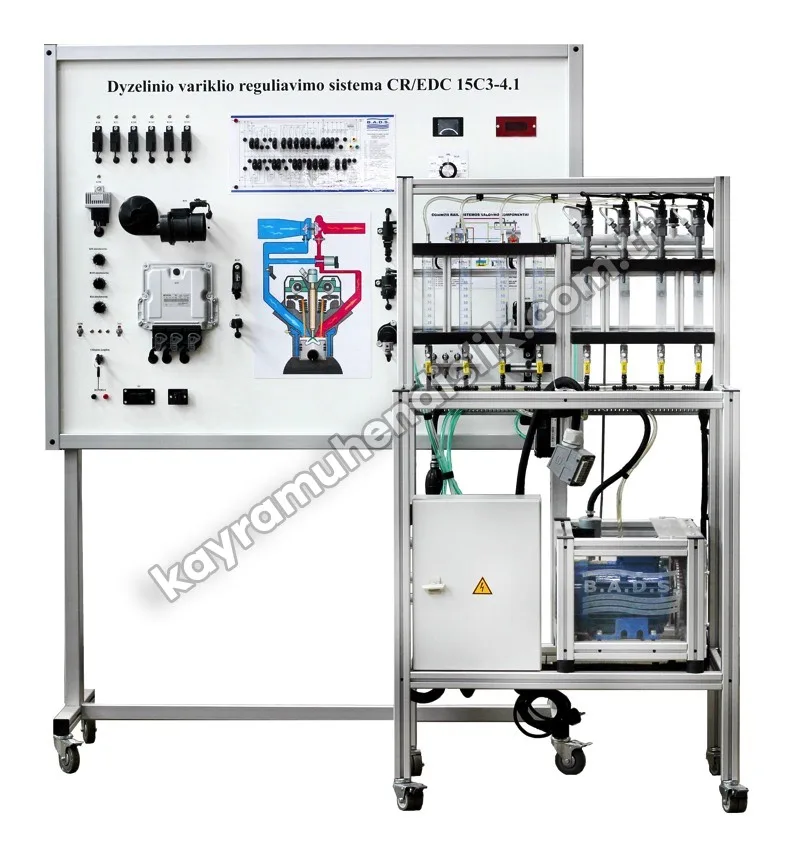
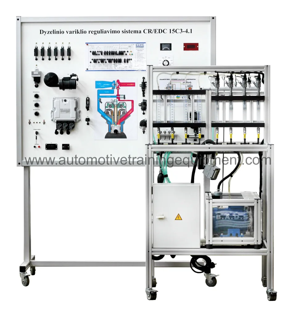
CR (Common Rail) EURO 4 Educational Diesel Engine Stand MVCR02
Ask About This ProductDescription
Educational Diesel Engine with CR System EURO 4 (Common Rail) MVCR2
Fully functional system
Diagnostics via OBD 16-pin diagnostic socket
Open contacts to measure system components and circuits
Fault code simulations
Description
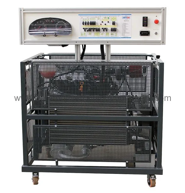
A stand-alone, fully operational diesel engine model mounted on a mobile frame. This training engine is specially designed to show the Common Rail diesel injection system and its operating structure. It is based on original (reconditioned) Renault components with the functional Bosch EDC 15 engine control system. The training engine is a great training tool that lets students learn the structure of the engine and its components, the power supply system, the cooling system and the engine control system. It also allows the components and operating modes of the engine control system to be studied and various measurements, tests and other diagnostic procedures to be carried out.
Technical specifications and functions
Functional engine model with CR fuel supply system, instrument panel, cooling system, power supply system and exhaust system;
Complete with removable safety panels for protection against hot and rotating parts;
Electrical wiring diagram with built-in banana-plug jumpers for measuring and simulating system fault codes;
Ability to simulate more than 20 faults by disconnecting the banana-plug jumpers;
Once the safety panels are removed, the engine with its external components is clearly visible. Easy access to the engine and its components for service and maintenance;
Integrated engine emergency stop button;
Oscilloscope / Multimeter
System parameters are measured by connecting to the banana connectors;
Ability to measure the electrical signal parameters of each system component (such as a signal or actuator);
Diagnostics and measurement
Oscilloscope / Multimeter
System parameters are measured by connecting to the banana connectors;
Ability to measure the electrical signal parameters of each system component (such as a signal or actuator);
Control unit diagnostics
Diagnostics via OBD 16-pin diagnostic connector
Electronic control unit (ECU) identification
Reading / clearing fault codes
Viewing operating system parameters (live data)
Actuator activation (depends on the control unit)
Throttle adaptation
Control unit coding / configuration
Delivery and Installation
Before shipment, our products are inspected and packed in special impact-resistant packaging, and are delivered safely to every province of Türkiye.
Installation: In laboratory and classroom projects, installation and commissioning after delivery are carried out by our expert team.
Training and support: User training and after-sales technical support are provided for experiment sets and simulators.